 Warning
Introduction
Young children begin to develop a basic knowledge about shapes as early as the toddler years. As we go through our day, we point out play things and environmental objects that have the shape of a circle, square, or rectangle. Long before a child can put a label on a shape, he can find objects and toys that are circles, or point to the picture of the circle, square, and so on, in a book. This type of learning is natural and fun for a young child and begins to build the foundation for mathematical skills and geometry.
In Foundations of Education, Second Edition, Volume II, Instructional Strategies for Teaching Children and Youths with Visual Impairments, Kapperman, Heinze, and Sticken write that “an understanding of mathematics is essential for full participation in society” (2000, p. 370).
The authors also point out that “students with visual impairments can gain a comprehension of basic mathematical concepts through the use of real objects and manipulatives,” and stress that “teachers of students with visual impairments teach the unique skills related to mathematics, such as, using an abacus and tactile graphics and collaborate with general education teachers to ensure that each student gains sound mathematical skills” (p. 370).
For the young child with a visual impairment, access to appropriate educational tools and the skills necessary for using them are crucial in the instruction of mathematics. Because mathematics is one of the more abstract and highly visual curriculum areas, teachers of the visually impaired must provide students with a variety of tangible objects and manipulatives that will make instruction meaningful. For the study of geometry, this involves tactile images and 3-D manipulatives that represent the basic concepts of geometry.
The Student Workbook, manipulative materials, and Teacher’s Manual provide the tools necessary for meaningful instruction of geometry for students who are visually impaired.
The Student Workbook revolves around three kinds of tasks. The first task is to familiarize students with various 3-D solids and their general properties. The second task is to help students grasp the difficult concepts of how 3-D solids relate to their 2-D graphic representations. Lastly, the third task is to help students understand how 3-D objects are made with 2-D objects.
Students will learn how to:
- Identify and tactually analyze 2-D shapes
- Identify, build, examine and tactually analyze 3-D solids
- Identify and compare the properties of 3-D solids, such as the number of faces, edges, and vertices
- Construct nets of 3-D solids
- Decompose 3-D solids into nets
- Identify and construct 2-D representations of a solid from varying perspectives
- Identify 2-D figures that are nets of 3-D solids
- Match tactile drawings of 3-D solids with tactile graphic nets
Activities in the Student Workbook for Geometro address the Principles and Standards for School Mathematics (National Council of Teachers of Mathematics) and the Common Core State Standards for Mathematics. Student Workbook for Geometro activities address the following National Council of Teachers of Mathematics Standards for Geometry.
Grades Pre-K to Grade 8:
- Analyze characteristics
Grades Pre-K to Grade 5:
- Visualization
Activities in the Student Workbook for Geometro address the following Common Core State Standards for Geometry.
Kindergarten:
- Identify and describe shapes
- Analyze, compare, create, and compose shapes
Grades 1-3:
- Reason with shapes and their attributes
We hope that you find these materials to be helpful, fun, and inviting for your students. Open the pages of the Student Workbook and watch your students learn!
Overview
The Student Workbook for Geometro is an extension and adaptation of the Net’s of 3-D Solids workbook commercially available from Geometro. With the addition of special exercises and tactile graphics, the Student Workbook for Geometro is designed for students who are blind and visually impaired. A set of manipulative materials containing rod models, magnetic tiles, a magnetic board, a Braille Pocket Folder, and a roll of Graphic Art Tape from APH, along with the Teacher’s Manual and the Student Workbook, make up Student Workbook for Geometro. Additionally, the activities in the workbook are to be used with Geometro tiles, which must be purchased separately from APH.
Description of Manipulative Materials
Rod Models
The rod models were developed by Geometro in order to better illustrate relationships between two- and three-dimensional aspects of solids; concepts that are notoriously difficult for students who are visually impaired.
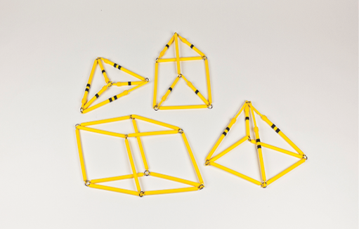
The rod models are made of plastic rods and are “skeletons” of 3-D solids with an edge length of about 4.5 in., matching the size of Geometro tiles. The models have two important properties. First, all joints are flexible, which makes the solids appear floppy and unable to stand on their own. Second, not all edges have a fixed length (i.e., some edges can extend beyond 4.5 in. and some can contract from 4.5 in.).
Four rod models are included: two prisms and two pyramids. In the models, vertices are flexible and there are three kinds of edges: fixed length, edges that shorten, and edges that lengthen.
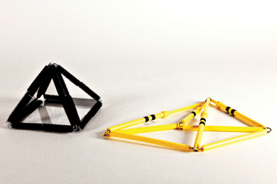
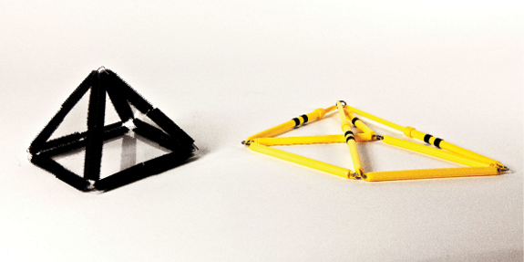
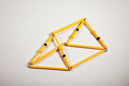
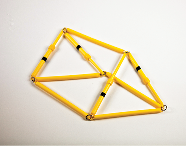
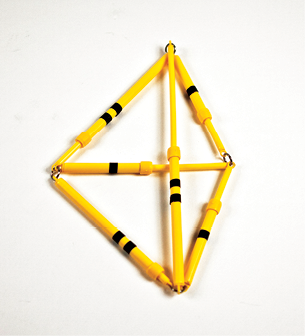
In order to improve communication of ideas, some edges of the rod models are labeled in the photos in this manual. The edges that can be shortened from 4.5 in. are labeled with one strip of ¼ in. Graphic Art Tape. Those that can be lengthened from 4.5 in. are labeled with two strips of ¼ in. Graphic Art Tape. Edges that are fixed length are not labeled. See Figure 1.
The edges of the rod models included with the Student Workbook are not labeled. We trust that teachers will quickly learn to recognize the three types of edges by their appearance and will be able to use the models without the labels. If desired, one can label the edges following the example and instruction contained here. A roll of Graphic Art Tape is included and can be used to label rod model edges if determined to be needed by a student. A suggested method for labeling, as seen in photos in this Teacher’s Manual: wrap two pieces of ¼ in. Graphic Art Tape around edges of rod model that can be lengthened from 4.5 in., placed approximately ¼ in. apart; wrap 1 piece of ¼ in. Graphic Art Tape around edges of rod model that can be shortened from 4.5 in. Colored electrical tape, available in hardware stores, is also efficient for this purpose.
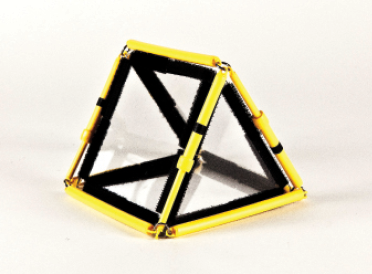
Rod models have flexible joints. The lengthening and shortening of edges is achieved by using telescopic junctions. In Figure 2 the edge marked with one strip of tape is made of two short rods; the edge marked with two strips of tape is made of two longer rods. The edges can also be easily identified by the length of the thicker rods instead of their tape labels; short for the collapsible edge with one strip of tape, and long for the extendable edge with two strips of tape.
The model’s flexible joints and the variable edge lengths serve one purpose: they make the models functional in both two and three dimensions. In other words, the models can be positioned upright as 3-D solids and then placed flat on a page to represent 2-D drawings of the same solid. The purpose is to illustrate, tactilely and kinesthetically, the relationship between a 3-D solid and its tactile drawing.
Rod models of the four simplest 3-D solids are included: two prisms and two pyramids. Because the details of edge shortening and lengthening that accompany the change from 3-D to 2-D are slightly different for each solid, and each has multiple 2-D representations, the models and their use are described individually in the next section.
Magnetic Tiles and Board
Magnetic tiles come as a set of six types of polygons—the same that are used throughout the Student Workbook—square, rectangle, pentagon, hexagon and two types of triangles, equilateral and isosceles. The magnetic tiles are designed with slightly raised edges for better tactile recognition. In addition, the size of the magnetic tiles is correlated with the size of the tactile drawings in the Student Workbook; therefore, the tiles fit inside the respective tactile drawings. This provides an additional step for students when analyzing and transferring the patterns between the manipulative materials.
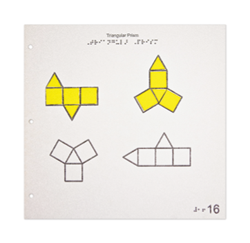
Figure 3 displays a page of tactile drawings from the Student Workbook with magnetic tiles fitted inside a tactile drawing for better recognition and transfer of the pattern.
The Student Workbook also includes a magnetic board on which the tiles can be assembled, manipulated, and stored for a period of time. An APH Braille Pocket Folder is included and can be used for storing the magnetic board with the student’s work. The purpose of including the magnetic tiles and board is to help students document their work, with the functionality similar to that of a drawing board, sketchpad, or a notebook.
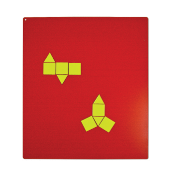
Figure 4 displays magnetic tile polygons arranged on a magnetic board for documentation and storage of student’s work.
Geometro Tiles
Geometro tiles are transparent plastic polygons with hook-and-loop material attached to their edges. The polygons join one to another by touching the hook to loop and loop to hook, respectively. The 3-D solids can be easily built using combinations of Geometro tiles.
Figure 5 shows a large set of Geometro tiles, available from APH.
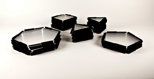
For the lessons described in this manual, the following polygons will be used: regular (equilateral) triangles, squares, pentagons, hexagons, isosceles triangles, and rectangles. Regular octagons and decagons are also available and can be used for extensions of the proposed lessons; but such exercises are not included in this Student Workbook.
Guide to Working with Rod Models
Why Are Rod Models Necessary?
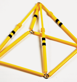
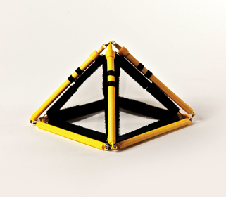
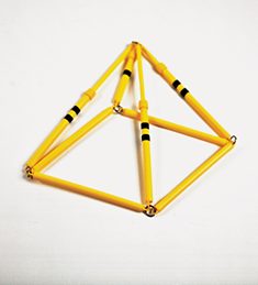
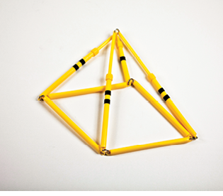
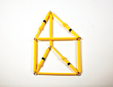
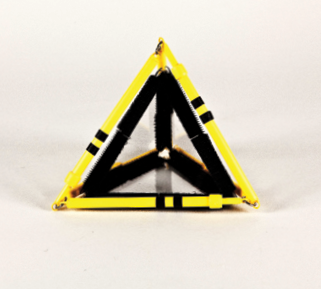
Although all the edges have equal length in the pyramid shown in Figure 6, they do not appear equal in the photograph.
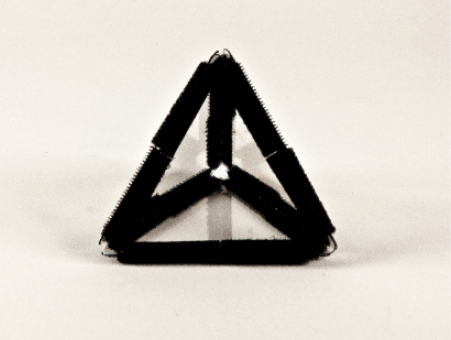
It is easy to observe that the pyramid consists of four equilateral triangles, and thus, all the edges have the same length. But look again! You may even use a ruler. The edges in the picture are not equal in length at all. One might say that it shows a triangle divided into three smaller triangles by three intersecting line fragments.
As Figure 6 illustrates, we are used to seeing objects in perspective; the fact that some edges become shorter and/or angles change does not disturb us. Our brains have learned to interpret with ease the shortening and lengthening of edges and changes in angles as a natural experience of viewing a 3-D object. We learned to recognize what the object is by the features it has, although it might look a bit different from a distance or from a different viewing angle. Often we even forget that the object looks different than what it is supposed to be! When we draw a 3-D object, we draw it the way it looks; we change the angles and the lengths of the edges. Again, our brains know that the drawing depicts a 3-D object. How do you convey this experience to someone who has never seen an object from a distance? This is a dilemma faced by every teacher of students who are visually impaired.
To help solve this problem, we decided to approach it from a literal standpoint. “Viewing” really means to make a projection of 3-D objects onto our retina. Drawing a 3-D object is very much the same; we make a 2-D representation on a piece of paper. The interpretation of these projections as 3-D objects happens in the brain.
So, to mimic this process, this set of materials includes 3-D models that are flexible enough to be placed flat on a surface. When placed flat, as with the process of drawing, some edges get shorter, some longer, and angles will change. This is what happens with the rod models. Most of the edges are constructed with telescopic junctions, so they can either shorten or extend. The vertices are fully flexible to allow changes in angles. This skeleton can be positioned upright as a 3-D object or placed flat on a surface to look like a 2-D drawing. The physical process of flattening the 3-D object gives kinesthetic understanding of why some edges have to change lengths and why angles have to change—because we want to make it flat. This is how a student with a visual impairment comprehends the idea of a drawing; from the kinesthetic and tactile input of repeatedly flattening and propping up the model. That is, switching between 2-D and 3-D.
Of course, we can view 3-D objects from different perspectives, and accordingly, we draw them differently. The same applies to folding; the rod models can be folded in different ways to reflect different perspectives.
However, it is one thing to look at an object and form a mental image, and a totally different matter to physically fold an object. The fact that we are dealing with physical objects (rods, rather than impressions) adds some constraints. Even more so if we are trying to help young children who are learning to “see.” We have to keep it simple. This is why the models are not strictly doing all that a true perspective demands. Also, they do not fold in every possible way (i.e., they do not portray every possible view; we simplified the engineering and use). Even with these limitations, there are many ways to fold and unfold the models; and the process will still help students develop ideas and concepts.
How to Use the Rod Models
This section focuses in detail on how to use each model so the teacher has the broadest possible understanding of a model’s use and limitations. Thus, the teacher can more easily tailor the lesson to the specific needs of a student.
There is a similar sequence of steps that we suggest for all models. Ask student to:
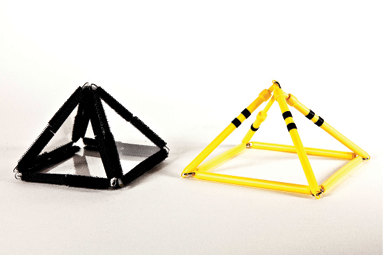
- Build a given 3-D solid using Geometro tiles.
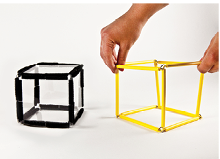
- Fit the rod models over the Geometro tiles in a specific way suggested for each solid and shown in the photographs.
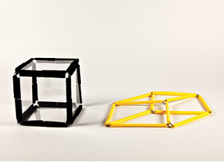
- Remove the rod model from the Geometro tile model and position it beside the tile model; support for some of the rod models will be necessary to keep them in a 3-D configuration.
- Place the rod model into a 2-D configuration with simultaneous extending or shortening of appropriate edges when necessary.
- Examine the 2-D configuration and compare it to tactile graphics for a given solid.
- Explore and discuss the origin of solid and dotted lines in the tactile drawings.
The models are described here in a sequence. For each model, there are two or three possible ways to form a 2-D configuration; they relate to the ways a solid can be viewed from different directions.
The examples of different positions for a given solid are shown in a series of photographs and descriptions. The examples reflect that there are many possible 2-D representations of a given 3-D shape. Sighted people experience this as viewing 3-D shapes from different perspectives, and are used to recognizing the 3-D shapes from their various 2-D representations. Since this experience is not typically accessible to students who are visually impaired, the tactile exercise of manipulating a 2-D rod model might help students to formulate the concept of origin, equivalency, and variability of such 2-D representations. The details of each configuration are not as important as the general idea that first, there are many possibilities and they correspond to many possible views of the same object; and second, the 2-D configurations “look/feel” quite different than the real 3-D objects. This is because the edge lengths and angles are changed. Of course, while recognition of some representations might be desired and certainly useful, we want to build the general ideas rather than detailed recognition. As always, the teacher can individually tailor the scope of a task to the needs of each student.
When we draw or photograph 3-D solids, we automatically pick directions of view that do not coincide with the solids’ axes of symmetry. Instead, we choose general directions, away from the symmetry axes. By doing so, we see more of the solid at once as all the edges and vertices can be visible because they do not overlap and/or screen each other. For example, when drawing a cube, we do not present it directly face-on; the result would be a picture of a square. Instead, we look slightly from the side and from the top or bottom; this way we see the eight vertices, 12 edges, and six faces all at once. This is also how we chose to position the models—slightly away from the most symmetrical orientations, as individually described.
Another interesting aspect of viewing a solid is that sometimes we do not actually see some edges fully; most typically if the solid is not a skeleton but a full solid. However, we know that the edges are there, and we reflect this fact by drawing the “invisible” edges with broken or dotted lines. These ideas and observations are inaccessible to a visually impaired person, as teachers know very well. However, it is necessary to help a child comprehend and interpret a tactile drawing that contains such broken lines. The idea that some edges are “obscured” by the front faces might be conveyed to a student with visual impairment by the process of folding and unfolding the rod models.
Square Prism (Cube)
The rod model for the cube is the simplest of the models. All 12 edges have the same fixed length, and all joints are flexible.
The cube model is also interesting in that it shows, contrary to our intuitive expectation, the cube is not stiff if the joints are flexible. This originates from the fact that a square is not stiff if it has flexible joints. In fact, a triangle is the only polygon that is stiff with flexible joints. This observation is sometimes missed since we tend to make cubes using materials that stiffen joints such as marshmallows, gummies, or peas. So, the customary stiff joints hide the fact that a cube is intrinsically flexible!
In a true perspective view of a cube, some of its edges really do change length. You can see this depicted in any photograph of a cube; for example, in starting position, Figure 8. The rod model is simplified and does not include this subtle change. Fortunately, the 2-D representation of the cube can be illustrated even with this simplification.
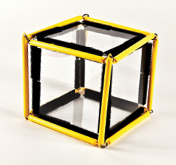
Square Prism (Cube), Starting Position
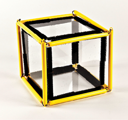
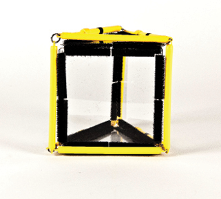
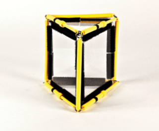
Starting position for the cube is with a square face in front and parallel to the viewer. However, this position is very symmetrical and a lot of the cube is not seen clearly. See Figure 7.
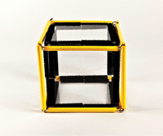
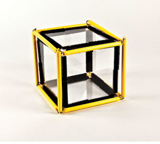
It is better to rotate the cube a little bit away from this symmetrical position and use the rotated position as a starting view, as illustrated in Figure 8 for the view from the left and Figure 9 for the view from the right.
Square Prism (Cube), Position 1
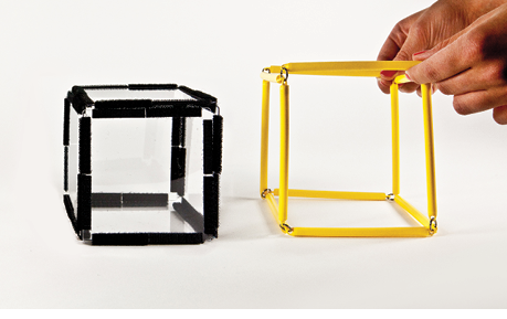
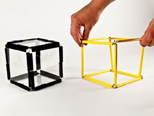
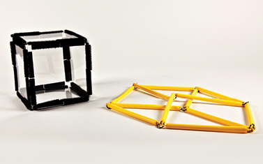
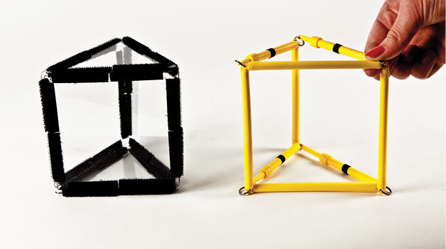
The cube is slightly rotated counter-clockwise from the starting, face-on position. See Figure 10.
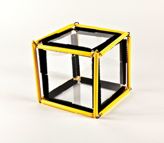
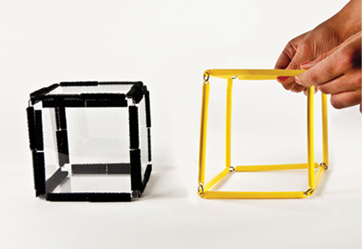
The rod model fits over the cube made with Geometro tiles. The rod model is then removed from the tiles. The 3-D cube made of the rod models is very floppy; as mentioned previously, it will not stand on its own and needs to be held in the vertical position. See Figures 10 and 11.
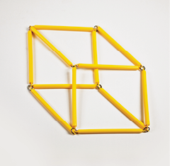
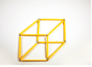
To obtain the most typical 2-D representation of the cube, it is best to change the shape of the base and top squares into rhombi before placing the model into the 2-D position. Elongate the squares along one of the diagonals as shown in Figure 12; then, place the cube on the surface by rotating the vertical edges away from the viewer. See Figure 13. The resulting configuration will look like that shown in Figure 14.
Square Prism (Cube), Position 2
The cube made of Geometro tiles is slightly rotated clockwise from the starting, face-on position. See Figure 15.
The rod model fits over the cube made with Geometro tiles. The rod model is removed from the tiles (Figure 16). The 3-D cube made of the rod models is very floppy; as mentioned previously, it will not stand on its own and needs to be held in the vertical position.
To obtain the most typical 2-D representation of the cube, it is best to change the shape of the base and top squares into rhombi before placing the model into the 2-D position. Elongate the squares along one of the diagonals as shown in Figure 17. Then, place the cube on the surface by rotating the vertical edges away from the viewer. See Figure 18. The resulting configuration will look like that shown in Figure 19.
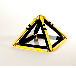
Square Pyramid
The square pyramid has eight edges. In the rod model, four edges at the base square have fixed length and are unmarked. The three edges that can extend are marked with two strips of Graphic Art Tape in the photos, and the one that can contract is marked with one strip of Graphic Art Tape.
Square Pyramid, Starting Position
The starting position for the square pyramid is with a vertical edge in front of the viewer and central. The rod model is fitted over the Geometro model so the fixed length edges form the base square and the only collapsible edge, marked with one strip of tape, is at the back of the pyramid, not visible in Figure 20.
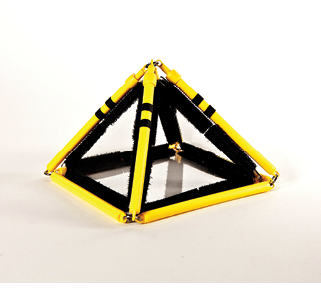
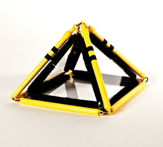
However, this position is very symmetrical and not all of the pyramid can be seen clearly. It is better to rotate the pyramid a little bit away from this symmetrical position and use the rotated position as a starting view, as illustrated in Figure 21 (counter-clockwise rotation), and Figure 22 (clockwise rotation).
Square Pyramid, Position 1
The square pyramid made of Geometro tiles is slightly rotated counter-clockwise from the starting, edge-on position. See Figure 23.
To demonstrate the 2-D representation, the rod pyramid can be taken off the Geometro model and laid flat by rotating the top vertex and placing it on the surface above the square. The edges that meet at the top vertex will change length in the process; the three at the front extend, the one at the back collapses, and the base square changes shape into a rhombus. See Figures 24-26.
Square Pyramid, Position 2
The square pyramid made of Geometro tiles is slightly rotated clockwise from the starting, edge-on position. See Figure 27.
To demonstrate the 2-D representation, the rod pyramid is taken off the Geometro model and laid flat by rotating the top vertex and placing it on the surface above the square. The edges that meet at the top vertex will change length in the process; the three at the front extend, the one at the back collapses, and the base square changes shape into a rhombus. See Figures 28-30.
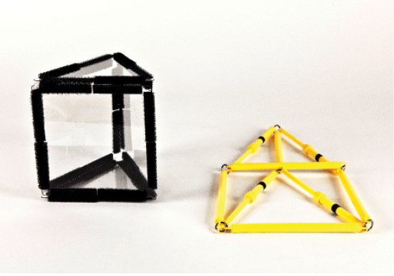
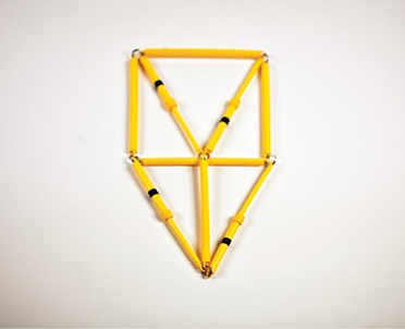
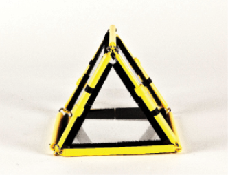
Triangular Prism
The triangular prism has nine edges. In its rod model, four of the nine edges can be shortened and are labeled with one strip of 1/4 in. Graphic Art Tape in the photos. The remaining five edges have fixed lengths and are unlabeled. We discuss three ways to look at the triangular prism, as shown below for three positions.
Triangular Prism, Position 1
The prism made of Geometro tiles is positioned with a square face in front, vertical, and parallel to the viewer. Two triangular faces are horizontal, and one of three vertical edges is at the back and central.
The rod model is fitted over the Geometro tiles with three unlabeled edges positioned vertically and two unlabeled edges horizontal to complete the front square. In the resulting configuration, each of the base triangles has one fixed length edge, parallel to the viewer, and two variable length edges, extending towards the back. See Figure 31.
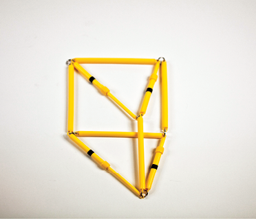
To collapse the 3-D rod model into 2-D, the model has to first be taken off the Geometro tiles. Since the joints are flexible, the rod model is not able to stand on its own as a 3-D structure once removed from the Geometro tiles, and therefore needs support to remain vertical. See Figure 32.
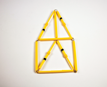
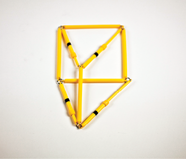
The rod model is now ready to be put into its 2-D configuration by rotating the vertical edges into horizontal positions and in a direction away from the viewer. By doing this, the top triangular face is placed above the bottom triangular face. In the 2-D configuration, the three parallel edges that were vertical in 3-D position must remain parallel. The respective edges of the bottom and top base triangles also have to remain equal and parallel. See Figure 33.
Please note that the transition from vertical to horizontal position is always performed away from the viewer, not toward the viewer. This intuitively corresponds with the fact that when we look at an object, the side that faces us always remains in view.
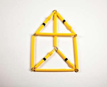
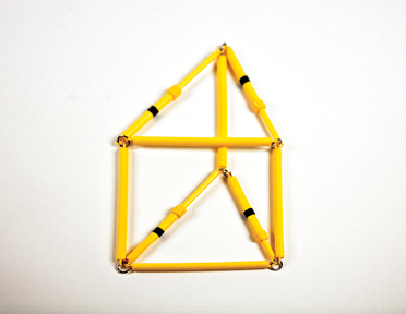
Since two edges of each of the base triangles have variable length, it is also possible to change the “look” of the prism by changing the lengths of these edges. This has to be done in pairs so that the front square keeps its shape. The resulting configurations correspond to different views of the prism, as if viewed from slightly different angles—more from the right or left. See Figures 34-37.
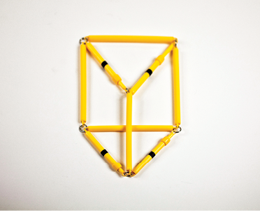
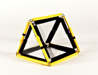
Triangular Prism, Position 2
The prism is positioned with a square vertical face parallel to the viewer and at the back. One of three vertical edges is in front and central. See Figure 38.
To obtain the 2-D configuration, the same steps for the previous position should be performed. Arrange the rod model over the Geometro tile model, take the rod model off, then rotate the vertical edges away from the viewer and place them in horizontal position. See Figures 39 and 40.
The resulting 2-D configuration corresponds to the view of the prism when viewed straight on. The views that correspond to looking from left or right are obtained by pair-wise shortening of the edges marked with one strip of tape. See Figures 41-44.
Triangular Prism, Position 3
This is a rather different and unusual starting position of the prism. The prism lies on a square side, with the two triangular faces vertical and facing the viewer. This position is not used in the Student Workbook. However, it is well worth introducing to the student with visual impairment since the triangular prism corresponds to important everyday objects such as roofs of buildings, and it helps to give a more comprehensive account. See Figure 45.
The position seen in Figure 45 is symmetrical and a lot of the solid cannot be seen clearly; it is better to rotate the model a little bit away from this symmetrical position and use the rotated position as a starting view. This is illustrated in Figure 46, view from the right and Figure 50, view from the left.
Other steps to obtain the 2-D configurations are as before: Arrange the rod model over the Geometro tile model, take the rod model off, then rotate the vertical edges away from the viewer to place them in horizontal position. See Figures 46-48 and 50-52. There is one additional step after Figures 47 and 51 that is not explicitly shown in the photographs; namely, the base square is changed into a rhombus by elongating one of the diagonals and shortening the other. After that, the prism is placed in the horizontal position, shown in Figures 48 and 52, respectively.
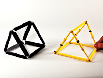
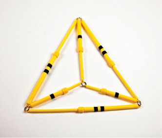
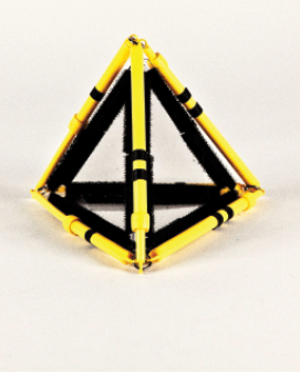
Triangular Pyramid
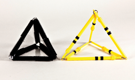
The triangular pyramid has six edges. In the rod model, all edges have variable length; three edges, labeled with one strip of Graphic Art Tape in the photos, can be shortened, and three, labeled with two strips of Graphic Art Tape, can extend. We discuss two ways to look at the triangular pyramid.
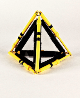
Triangular Pyramid, Position 1
The triangular pyramid is positioned with a face parallel to the viewer and in front. An edge is at the back and center.
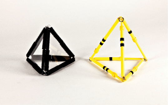
The rod model should be fitted over the Geometro model so the three extendable edges fit over the front triangle while the collapsible edges go toward the back. See Figure 54.
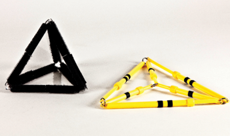
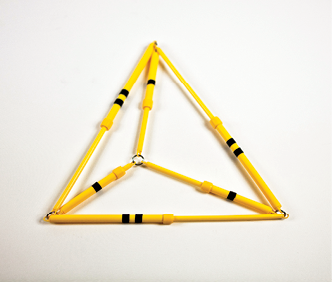
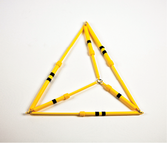
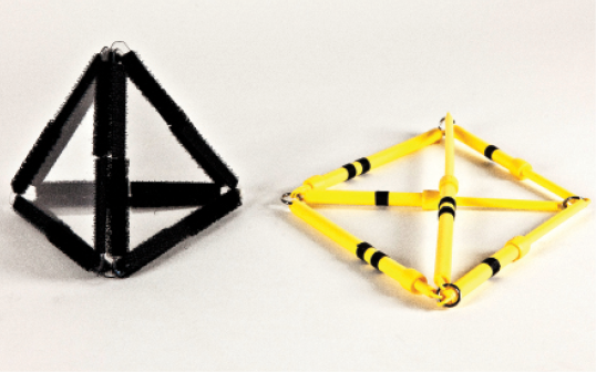
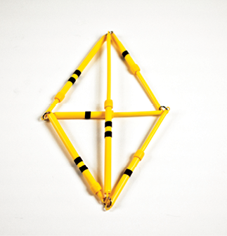
To transform the 3-D rod model into 2-D, the rod model must be taken off the Geometro tiles and, subsequently, the top vertex placed on the surface above the base triangle. In the process, the edges marked with one strip of tape will shorten while the edges marked with two strips of tape extend a little. See Figures 55-57.
The less symmetrical views of the pyramid can be obtained by further shortening one of the collapsible edges, as shown in Figures 58 and 59.
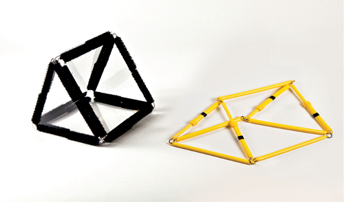
Triangular Pyramid, Position 2
The triangular pyramid is positioned with a face parallel to the viewer and at the back. An edge is in front and center.
The rod model is placed over the Geometro model with an extendable edge, marked with two strips of tape in the photos, front and center. The remaining edges may be arranged as shown in Figure 60 or 61.
To form the 2-D projection, the top vertex is placed on the plane above the base triangle, for which the front edge (marked with two strips of tape) needs to be maximally extended. The back horizontal edge (marked with one strip of tape) may be slightly collapsed at the same time. See Figures 62-64.
A less symmetrical view of the pyramid can be obtained by shortening the other two collapsible edges marked with two strips of tape, as shown in Figure 65.
The Pedagogical Process—Four Lessons with the Triangular Prism
The overall goal of the Student Workbook is to help students who are visually impaired form the best possible intuitive understanding of basic spatial concepts, especially the relationships between aspects of three- and two-dimensional objects.
The Student Workbook is divided into four types of lessons, roughly one lesson per page, that offer a similar set of activities for different 3-D solids. The four lessons are specified in step-by-step detail in the Teacher’s Guide section of the Student Workbook. Here the lessons are discussed in detail in order to give the teacher necessary background and supporting information for providing instruction.
There are opportunities for repetition and also flexibility for the teacher to choose a lesson and/or a solid at a level that is appropriate for a student. This allows for teachers to offer enough practice and to check student progress.
Let’s look at the four lessons using one of the solids in the workbook—the triangular prism—as an example.
Lesson 1:
Understanding 2-D Tactile Drawings of 3-D Solids
- Ask the student to make a triangular prism using Geometro tiles; or alternatively, offer a ready-made solid for student’s examination.
- Position the Geometro model of the triangular prism in one of the positions described in the section dealing with this solid; that is, position 1 or 2. Here it is shown in position 1, in Figure 66.
Figure 66. 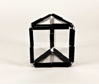
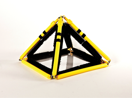
Fit the rod model of the triangular prism snuggly on the prism made of Geometro tiles, as in Figure 67. Let the student examine this configuration.
Figure 67. 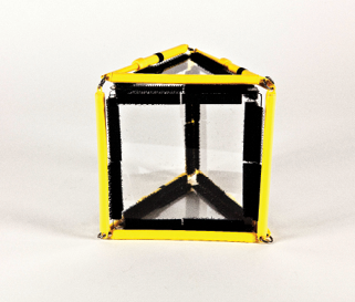
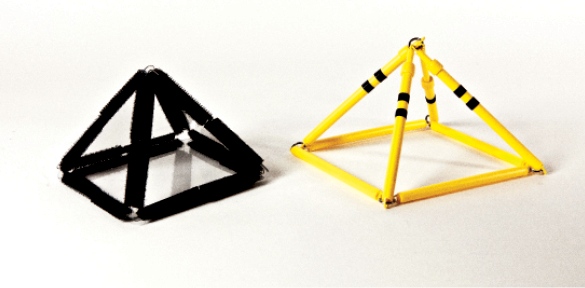
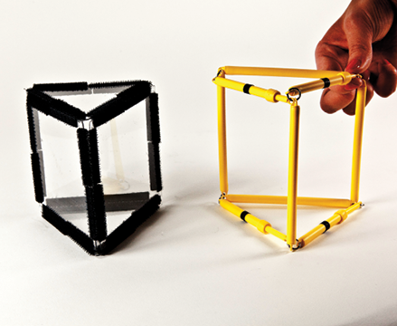
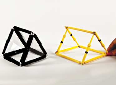
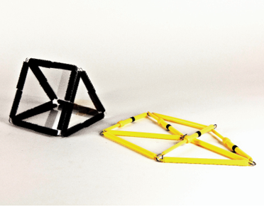
- Remove the rod model from the Geometro model and position the two side by side. The rod model may have some difficulty standing on its own, so you might have to support it. Let the student examine both models. See Figure 68.
Figure 68. 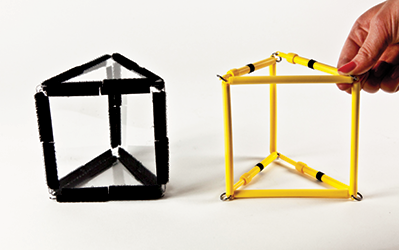
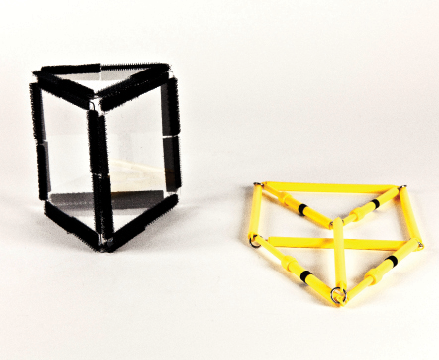
- Now, the most important part! Slowly place the rod model of the prism flat on the table. The flexible joints will allow the range of motion. See Figure 69.
Figure 69. 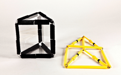
- Raise the prism into 3-D by reversing the above steps. Place it flat again, into 2-D. Repeat as many times as required for the student to understand WHY the 2-D drawing functions the way it does. The triangular prism can be put into 2-D without changes in the length of the rods (see Figure 70). However, it does not look the way we normally see it; the edges marked with one strip of tape should be shortened (see Figure 71). After the student becomes familiar with the idea of the 2-D appearance of the prism, the teacher can introduce the step to shorten the edges marked with one strip of tape. However, for other solids, there will be edges that have to be shortened or elongated to be able to put the solid into 2-D.
In each case, it is very important to let the student feel how some edges have to shorten and some elongate in the process of going from 3-D to 2-D.
Figure 70. 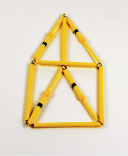
Figure 71. 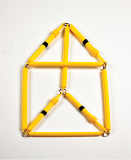
- Ask the student to examine the large tactile drawing of the solid on page 13 of the Student Workbook. Notice that there are solid and dotted lines on the drawing.
- Examine the 2-D rod model of the solid and determine which edges may be “hidden” in the flat configuration and, therefore, correspond with dotted lines on the tactile drawing.
- The large tactile drawing on page 13 of the Student Workbook matches the dimensions of the rod model when in 2-D configuration. The task for the student is to superimpose the 2-D rod model onto the large tactile drawing. Adjusting the lengths of the edges might be required for some solids.
Figure 72 depicts a page with a tactile drawing from the Student Workbook showing a rod model superimposed on the tactile drawing of a triangular prism, demonstrating the origin of a 2-D tactile drawing.
Figure 72. 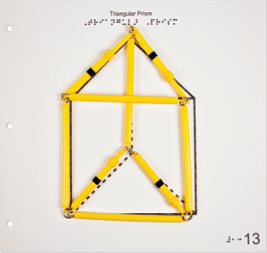
- After the student becomes familiar with the process of folding and unfolding the 3-D to 2-D, and thus, the origin of the large tactile representation, ask the student to examine the same, but smaller, tactile drawings on page 15 of the Student Workbook. Notice the orientation of the two solids on the page; only one corresponds to the drawing on page 13.
- Page 14 of the Student Workbook is essentially the same exercise; however, now the 3-D prism is folded to 2-D a bit differently by following the instructions for position 2 of the triangular prism. Visually, we recognize with no difficulty at all that the drawing represents the same prism. A student with visual impairment, especially one who is congenitally visually impaired, may not comprehend how the two representations on pages 13 and 14 of the Student Workbook show the same solid. The two exercises convey the idea that a 3-D object will look different when viewed from different directions; the same way the rod model may look and feel different when folded in various ways. Ask the student to examine the two small tactile drawings on page 15 of the Student Workbook. Compare the orientation of both solids on page 15 to corresponding drawings on pages 13 and 14.
Lesson 2
Decomposing 3-D Solids into Nets
- Ask the student to identify the 3-D solid represented by the tactile drawing on page 13 of the Student Workbook as a triangular prism. Or alternatively, present the student with a ready-made model of a triangular prism.
- Ask the student to decompose the Geometro tile model so it lies flat, forming a net.
- Ask the student to record the net on the magnetic board using the magnetic (tile) polygons.
- Ask the student to put the Geometro model back into 3-D and then decompose again, forming a different net.
- Before recording each new net on the board, the student must make sure that the same net isn’t recorded there already. For the simplest solid, such as the triangular pyramid, there is little challenge in this exercise since there are few different nets possible. However, for most solids, many nets are possible. For example, a cube has 11 possible nets. The challenge is in discovering them all and making sure that they are all unique. It may be a challenge for the student to decide on the “simple” fact of whether two nets are different or the same. If one of two identical nets is rotated or flipped (reflected), it may not be immediately obvious that they are identical. This could be a demanding, but worthy, exercise for a student with visual impairment.
- After establishing that a new net is different from all previously recorded ones, ask the student to record each new net.
- Steps 4-6 can be repeated, as many times as appropriate.
Lesson 3
Choosing Nets for 3-D Solids
This lesson is a reversal of Lesson 2. The student is presented with a series of 2-D tactile figures and must decide if each can be folded into a 3-D solid (i.e., if the arrangement is a net for the solid).
- Ask the student to identify the 3-D solid represented by the tactile drawing on page 13 of the Student Workbook. Or alternatively, present the student with a ready-made model of the solid.
- Ask the student to examine the tactile drawings of the 2-D figures on page 16.
- The task for this lesson is to identify, and indicate, which of the four 2-D figures can be folded into a triangular prism (i.e., which are the nets for the triangular prism).
- Depending on age and/or abilities, a student may work without manipulatives, or use Geometro tiles to check the predictions. If the student has difficulty transferring the pattern from the tactile drawing to Geometro tiles, it is suitable to use the magnetic tiles as an intermediary. The magnetic tiles fit inside the respective tactile drawings and they may help a student better understand the pattern of each 2-D figure; transfer to Geometro tiles if necessary.
Figure 73 depicts a page of tactile drawings from the Student Workbook, with magnetic tiles fitted inside some of the tactile 2-D figures for better recognition and transfer of the pattern, and for better understanding the pattern of the 2-D figures.
Figure 73. 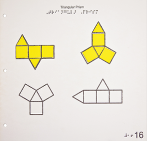
- After the pattern of the 2-D figure is transferred from the tactile drawing to Geometro tiles, the student will be able to check, by folding the tiles, if the prism can be obtained from the 2-D figure.
- Ask the student to indicate the 2-D figures that can be folded into the triangular prism.
Lesson 4
Changing 2-D Figures So They Can Be Folded into a Solid
Only two of the four 2-D figures from Lesson 3 (shown on page 16 of the Student Workbook) can be folded into a triangular prism. The other two 2-D figures require some changes in order to do so. Neither of the two 2-D figures on page 17 can be folded into a triangular prism; both require some changes. The object of this lesson is to arrive at, and describe, the necessary changes.
- Ask the student to identify the 3-D solid represented by the tactile drawings on page 13 of the Student Workbook. Or alternatively, present the student with a ready-made model of the solid.
- Ask the student to examine tactile drawings of 2-D figures on page 17 of the Student Workbook.
- Ask the student to construct the same 2-D figures using Geometro tiles and check if the figure can be folded into the identified solid.
- If needed, it may be useful for the student to initially place the magnetic tiles inside the polygons on the tactile drawings of the 2-D figures.
- Ask the student to determine why the 2-D figures will not fold into the 3-D triangular prism, and indicate how to change them so they will fold correctly.
Generally, throughout the book, the nature of necessary changes can vary. The 2-D figures may need more or fewer polygons, they may need a re-arrangement of the polygons, or they may have wrong polygons that need to be exchanged. Combinations of the above could also appear in some cases.
For example, if we look at the 2-D figures for the triangular prism on page 17 of the Student Workbook, the first figure has a correct number of polygons (i.e., three squares and two triangles), but they are arranged incorrectly. The student needs to change the position of one of the triangles and choose where to put it to form a net. The second 2-D figure, on the other hand, has too few polygons; one triangle is missing, and the student has to decide where to place an extra triangle to form a net.
- The magnetic tiles can be used for the construction of the net on the magnetic board. The magnetic board will hold the tiles sufficiently and strongly in place so that it can be inserted into the Braille Pocket Folder, which can then be placed in the Student Workbook and referred to later.
- The final step of the lesson is for the student to write a description of the changes needed to make the 2-D figures become nets. This provides an excellent opportunity to develop and use space-related vocabulary and expressions.
A student can use a journal or other notebook to record the descriptions, or use any other method agreed upon by student and teacher.
Additional Activities
- Exploring general properties of solids: This exercise could be either an initial or final activity related to each solid. The student may count and record the number of faces, edges, and vertices and specify what polygons are used to make a solid.
To help with the counting and sequence of steps, the student may use markers—removable stickers for faces and some hook-and-loop material markers for edges and vertices.
Figure 74 depicts hook-and-loop material markers, available from Geometro, used to help count edges and vertices of a solid made from Geometro tiles. Figure 75 depicts stickers used to help count faces of a solid.
Figure 74. 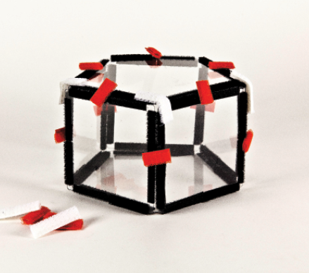
Figure 75. 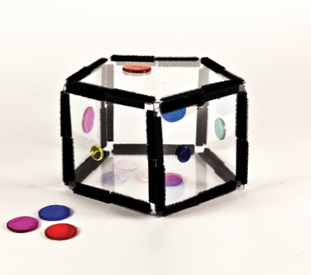
There is a simple relationship between the number of faces (F), vertices (V), and edges (E) that applies to every solid, as discovered by the Swiss mathematician, Leonhard Euler. The relationship, known as the Euler equation is: V-E+F=2. As an additional task, a student may either check the equation for a particular solid or arrive at the relationship after collecting the data for a number of solids. - Exploring diagonal lines in a cube: It is easy to diagonally insert a soft rod through the opening of the vertices of the cube and make the rod available for tactile inspection by a student. If four such rods are inserted through corresponding vertices, the four diagonal lines of the cube are formed. They too can be explored tactually to examine their relative position and their point of intersection in the middle of the cube, as seen in Figure 76.
Figure 76 depicts plastic rods, available from Geometro, inserted through the vertices of a cube to indicate four diagonals and illustrate that they cross in the center of the cube. The diagonals can be inspected tactually.
Figure 76. 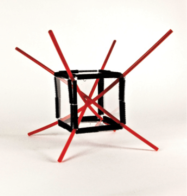
- Exploring directions of lines: The concepts of parallel, perpendicular, and skew directions can be introduced and/or reinforced by examining the relative positions of the edges of various solids. To enhance the perception of direction in space, hook-and-loop material rods (available from APH) or other rods may be used, as shown in Figure 77.
Figure 77 depicts hook-and-loop material rods attached to the parallel, perpendicular, and skew edge pairs of the cube to accentuate the corresponding spatial relationships.
Figure 77. 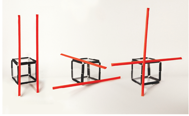
References
Kapperman, G., Heinze, T., & Sticken, J. (2000). Mathematics. In A. J. Koenig & M. C. Holbrook (Eds.), Foundations of education: Instructional strategies for teaching children and youths with visual impairments (2nd ed., Vol. II, pp. 370-399). New York: American Foundation for the Blind.